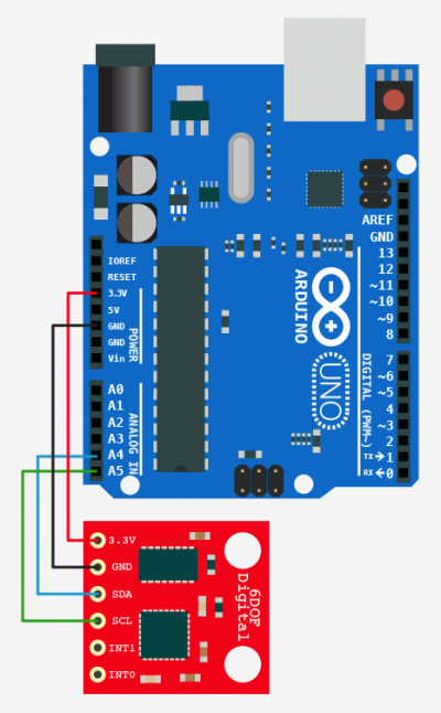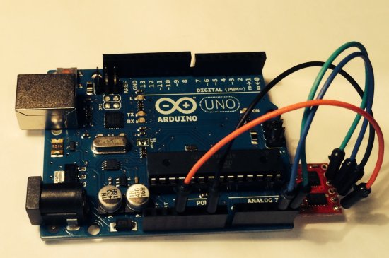
You can get a pretty good IMU board for under a hundred dollars. The illustration above shows the hookup I am using to get started with IMU data processing. The Arduino (blue) controller board above is a general purpose device that contains an onboard CPU chip which you can program using a fee cross compiler on your PC. I bought the Arduino Uno at Radio Shack as part of a package called "Arduino Starter Kit." I ordered the 6DOF Digital (red) board from Karlsson robotics for $65. Later, I found out the same unit is available from Sparkfun for $35.

The IMU board finally showed up on Monday and I was eager to find
out if I could pass the first hurdle: wire the IMU up and program
the Arduino to read data from it. Fortunately, there is ready
made Arduino code that I could use for testing. You can view the
source code here. This sample by Kristian Lauszus appears to be
intended as a platform leveler and it includes a Kalman filter that combines the accelerometer data
and the gyro data to measure the attitude of a platform relative to the horizontal plane.
For a navigation application, we need to get the gyro and accelerometer data out to another computer
so we can combine it with our GPS position fixes from the Garmin GPS-12. Lauszas code was a good starting point, so I modified it to write the gyro rate and accumulated angle data out to serial
port. My program (or "Sketch" as the Arduino folks prefer to call it) looks like this:
#include
#define gyroAddress 0x68
#define adxlAddress 0x53
double zeroValue[6] = { 0,0,0,38,31,-16}; // Found by experimenting
/* All the angles start at 0 degrees */
double gyroXangle = 0;
double gyroYangle = 0;
double gyroZangle = 0;
unsigned long timer;
void setup() {
  Serial.begin(115200);
  Wire.begin();
  i2cWrite(gyroAddress, 0x16, 0x1A); // this puts your gyro at +-2000deg/sec  and 98Hz Low pass filter
  i2cWrite(gyroAddress, 0x15, 0x09); // this sets your gyro at 100Hz sample rate
  timer = micros();
}
void loop() {
  double seconds = (double)micros()/1000000;
  double gyroXrate = -(((double)readGyroX() - zeroValue[3]) / 14.375);
  gyroXangle += gyroXrate * ((double)(micros() - timer) / 1000000); // Without any filter
  double gyroYrate = (((double)readGyroY() - zeroValue[4]) / 14.375);
  gyroYangle += gyroYrate * ((double)(micros() - timer) / 1000000); // Without any filter
  double gyroZrate = (((double)readGyroZ() - zeroValue[5])/ 14.375);
  gyroZangle += gyroZrate *((double)(micros() - timer)/1000000);
  timer = micros();
  /* print data to processing */
  Serial.print(seconds); Serial.print("\t");
  Serial.print(gyroXrate); Serial.print("\t");
  Serial.print(gyroYrate); Serial.print("\t");
  Serial.print(gyroZrate); Serial.print("\t");
  Serial.print(gyroXangle); Serial.print("\t");
  Serial.print(gyroYangle); Serial.print("\t");
  Serial.print(gyroZangle); Serial.print("\t");
  Serial.print("\n");
  delay(10);
}
void i2cWrite(uint8_t address, uint8_t registerAddress, uint8_t data) {
  Wire.beginTransmission(address);
  Wire.write(registerAddress);
  Wire.write(data);
  Wire.endTransmission();
}
uint8_t* i2cRead(uint8_t address, uint8_t registerAddress, uint8_t nbytes) {
  static uint8_t data[12];
  Wire.beginTransmission(address);
  Wire.write(registerAddress);
  Wire.endTransmission();
  Wire.beginTransmission(address);
  Wire.requestFrom(address, nbytes);
  for (uint8_t i = 0; i < nbytes; i++)
    data[i] = Wire.read();
  Wire.endTransmission();
  return data;
}
int readGyroX() { // This really measures the x-axis of the gyro
  uint8_t* data = i2cRead(gyroAddress, 0x1D, 2);
  return ((data[0] << 8) | data[1]);
}
int readGyroY() { // This really measures the y-axis of the gyro
  uint8_t* data = i2cRead(gyroAddress, 0x1F, 2);
  return ((data[0] << 8) | data[1]);
}
int readGyroZ() { // read z axis of the gyro
  uint8_t* data = i2cRead(gyroAddress,0x21, 2);
  return ((data[0] << 8) | data[1]);
}
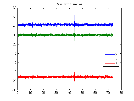
Here is a plot of the raw gyro rate data.

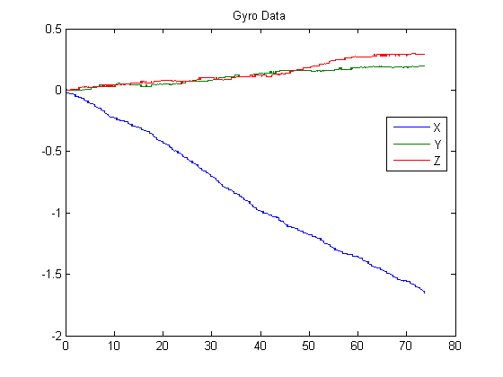
The following plot shows accumulated drift over 75 seconds.

These results look pretty good. I had previously reported seeing large anomalous spikes
in the gyro rate data, but that appears to be due to a memory problem which has been corrected in the sample source code included.
In the course of my testing of the hardware, I have observed changes in the gyro biases
from one session to another of about 25%. It seems likely that the application software
will need to go through a bias computation phase during startup in order to achieve good
navigation results.
Next update, we'll take a look at the accelerometer data.
Thanks for visiting my web-site -- Cary Semar
Return to Index
| 


