|
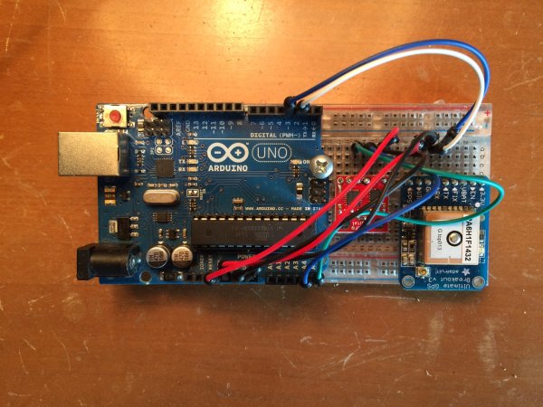
The next step is to combine the MTK3338 GPS chip with the ADXL335 IMU chip and collect data
simultaneously, using the Arduino Uno as an interface device. As shown in the photo, the IMU and GPS chip are mounted on a breadboard and then wired to the interface pins on the Arduino Uno. The GPS data connections are TX ( blue wire) to pin 3 on the Uno and RX (white wire) to pin 2 on the Uno. Here is the arduino code used to collect data from both the GPS and the IMU. As before (see 8/27/2014 posting) the IMU data pins (SDA and SDL) are connected to the analog pins A4 and A5 on the Arduino (respectively).

#include   // Install Adafruit GPS library
#include  // Include serial library
#include
#define gyroAddress 0x68
#define adxlAddress 0x53
SoftwareSerial MySerial(3,2);  // Create serial port on pins 3,2
Adafruit_GPS GPS(&MySerial);   // Create serial objct
String NMEA1;
String NMEA2;
String NMEA3;
unsigned long timer;
unsigned long timer1;
unsigned long timer2;
double dt;
char c;          // a char from GPS

void setup() {
  Serial.begin(115200);   // start output to computer
  Wire.begin();
  i2cWrite(adxlAddress,0x31,0x09);  // Full resolution mode
  i2cWrite(adxlAddress,0x2D,0x08);  // set ADXL345 for const. meas. mode
  i2cWrite(gyroAddress, 0x16, 0x1A); // this puts your gyro at +-2000deg/sec  and 98Hz Low pass filter
  i2cWrite(gyroAddress, 0x15, 0x09); // this sets your gyro at 100Hz sample rate
  GPS.begin(9600);        // start input from GPS
  GPS.sendCommand("$PGCMD,33,0*6D"); // turn off antenna status out
  GPS.sendCommand(PMTK_SET_NMEA_UPDATE_5HZ); // set output rate
  GPS.sendCommand(PMTK_SET_NMEA_OUTPUT_RMCGGA); //select messages
  delay(100);   // let it settle down.
  readGPS();
  readGPS();
  timer = micros();
}

void loop() {
  int i;
  int rawGyro[3];
  int rawAccel[3];
  static double body_rate[3];
  static double body_accel[3];
  static int nsamples = 0;
  c = GPS.read();
  if((int)c != 0) {
     timer2 = micros();
     readGPS();
     Serial.print(NMEA1);Serial.print(NMEA2);Serial.print("\n");
     Serial.print(nsamples);Serial.print("\t");
     dt = (double)(timer2-timer1)/1000.0;
     Serial.print(dt);Serial.print("\t");


     if(nsamples>0) {
       timer1 = micros();
       for(i=0;i<3;++i) {
         body_rate[i] = body_rate[i]/(double)nsamples;
         body_accel[i] = body_accel[i]/(double)nsamples;
       }
     }
     for(i=0;i<3;++i) {
      Serial.print(body_rate[i]); Serial.print("\t");
     }
    for(i=0;i<3;++i) {
      Serial.print(body_accel[i]);Serial.print("\t");
    }
     Serial.print("\n");
     nsamples = 0;
  }
  rawGyro[0] = readGyroX();
  rawGyro[1] = readGyroY();
  rawGyro[2] = readGyroZ();
  rawAccel[0] = readAccX();
  rawAccel[1] = readAccY();
  rawAccel[2] = readAccZ();
  if(nsamples==0) {
     for(i=0;i<3;++i) {
       body_rate[i] = 0.0;
       body_accel[i] = 0.0;
     }
  }
  for(i=0;i<3;++i) {
    body_rate[i] += (double)rawGyro[i];
    body_accel[i] += (double)rawAccel[i];
  }
  ++nsamples;
  //Serial.print(rawGyro[0]); Serial.print("\t");
  //Serial.print(rawGyro[1]); Serial.print("\t");
  //Serial.print(rawGyro[2]); Serial.print("\t");
  //Serial.print(rawAccel[0]);Serial.print("\t");
  //Serial.print(rawAccel[1]);Serial.print("\t");
  //Serial.print(rawAccel[2]);Serial.print("\n");
  //delay(20);
}
void readGPS() {
  while(!GPS.newNMEAreceived()){
    c = GPS.read();
  }
  NMEA1 = GPS.lastNMEA();
  while(!GPS.newNMEAreceived()){
    c = GPS.read();
  }
  NMEA2 = GPS.lastNMEA();
}
void i2cWrite(uint8_t address, uint8_t registerAddress, uint8_t data) {
  Wire.beginTransmission(address);
  Wire.write(registerAddress);
  Wire.write(data);
  Wire.endTransmission();
}
uint8_t* i2cRead(uint8_t address, uint8_t registerAddress, uint8_t nbytes) {
  static uint8_t data[2];
  Wire.beginTransmission(address);
  Wire.write(registerAddress);
  Wire.endTransmission();
  Wire.beginTransmission(address);
  Wire.requestFrom(address, nbytes);
  for (uint8_t i = 0; i < nbytes; i++)
    data[i] = Wire.read();
  Wire.endTransmission();
  return data;
}
int readGyroX() { // This really measures the x-axis of the gyro
  uint8_t* data = i2cRead(gyroAddress, 0x1D, 2);
  return ((data[0] << 8) | data[1]);

}
int readGyroY() { // This really measures the y-axis of the gyro
  uint8_t* data = i2cRead(gyroAddress, 0x1F, 2);
  return ((data[0] << 8) | data[1]);
}
int readGyroZ() { // read z axis of the gyro
  uint8_t* data = i2cRead(gyroAddress,0x21, 2);
  return ((data[0] << 8) | data[1]);
}
int readAccX() {
  uint8_t* data = i2cRead(adxlAddress, 0x32, 2);
  return (data[0] | (data[1] << 8));
}
int readAccY() {
  uint8_t* data = i2cRead(adxlAddress, 0x34, 2);
  return (data[0] | (data[1] << 8));
}
int readAccZ() {
  uint8_t* data = i2cRead(adxlAddress, 0x36, 2);

  return (data[0] | (data[1] << 8));
}
This algorithm uses the free ADAfruit_GPS library which can be downloaded from their website.
The output from the Arduino looks like this:
$GPGGA,153921.800,2930.1272,N,09456.5033,W,1,04,1.83,-21.1,M,-23.9,M,,*4A
$GPRMC,153921.800,A,2930.1272,N,09456.5033,W,0.04,78.82,101015,,,A*49
9	71.65	21.78	36.33	3.67	-0.22	14.22	271.00

$GPGGA,153922.000,2930.1272,N,09456.5033,W,1,04,1.83,-21.1,M,-23.9,M,,*41
$GPRMC,153922.000,A,2930.1272,N,09456.5033,W,0.04,124.68,101015,,,A*7E
9	72.52	21.89	36.00	4.00	-0.33	14.33	270.67
For our application, we are using the sentences GPGGA and GPRMC. The first sentence provides GPS position fixes, but the second also gives speed in knots and true course which ultimate should prove useful.
The third line is the formatted output from the IMU. The main loop of the Arduino code first checks to see if there is GPS data ready to transmit. If not, the Arduino samples the IMU data and sums the gyro and accelerometer counts. When GPS data is available, the GPS data is read and output, the IMU data is averaged and written to the output.
The first number is the number of microseconds over which the IMU data is averaged. The next three numbers are the average of the gyro data, followed by the average of the accelerometer data.
Return to Index
|
